![]()
13721 Spring Hill Dr., Spring Hill, FL 34611
Phone: 352
688 8160 M-F EST
PROWLER STAINLESS BUMPER REMOVAL
FAIRINGS with LIGHTS
Part#
822026
INSTRUCTIONS
Note You can view our installation VIDEO on our website under the
Bumper Removal Fairing Item. Click Installation Video.
https://theprowlerstore.com/Products_Page_Parts_Upgrades_Bumper_Removal_Fairings.htm
or on YouTube at:
www.youtube.com/user/americancarcraft#p/a/u/0/lb3mG5MWQrU
 PARTS INCLUDED:
2 x Stainless Bumper Fairings w/Lights
2 x Adhesive Promoter Packs
2 x Long Lengths of Chrome Trim 23”
2 x Short Lengths of Chrome Trim 14”
2 x Large Self Stick Brackets
2 x Small Self Stick Brackets
4 x 1/4” 20 Nut & Bolt
14 x Blue Wire Connectors
2-Stainless 10/32 Phillips Screws
1-Pair of Plastic Gloves
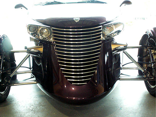
The new prowler bumper fill are the first of its kind. A truly custom accessory designed to compliment and complete our stainless steel front suspension cover kit. This kit should be professionally installed due to the difficulty and due to the fact that the kit will need to be manually formed to the body. This will require some customizing skill in order to achieve a nice contoured installation.
Installation instructions
Fairing Assembly
Your new kit comes with a partial protective liner; do not remove until
prompted by instructions. You have been provided with a pair of plastic
gloves to eliminate finger prints and possible scratches during
installation.
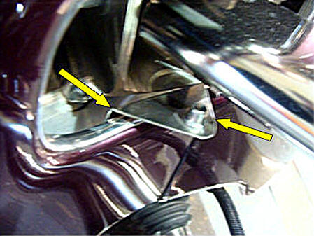
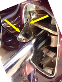
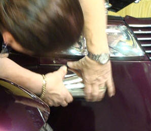
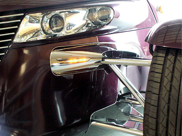
1. The first step is to remove the factory bumpers. Take a look at the attachment bolts of each bumper located just to the right and left sides of the battery. You will notice that three of the four bolts are relatively easy to get to. Detach these three bolts. Once these three bolts have been removed you will be able to rotate the entire bumper downward to expose the remaining bolt at the top outer corner of the bumper bracket. To access this bolt you will need to use a 1/4’’ drive short socket attached to a swiveled adapter on a long extension. This will allow you to sneak into this bracket valley from the outside of the Prowler and detach the final bolt. It would be very helpful to have a friend support the bumper as you are removing the bolt. Manipulate the bumper out of the body opening and then detach the electrical connector.
2. Now that the bumpers have been removed the next step will be to prepare the opening for the new filler. Thoroughly scrub clean the inner surface area of the front fender just in front of the bumper attachment bracket. And also inside of the small opening of the rear arm bushing. This small opening is a little tricky to access but must be thoroughly cleaned to remove any and all road grime and dirt. Also scrub the fender rims of both openings. Once these areas have been thoroughly cleaned on both sides of the Prowler swipe all the areas once with the adhesive promoter provided. Finally clean the front of the aluminum bumper bracket and swipe it with the adhesive promoter as well.
Picture 1
Picture
2
Picture 3
Picture 4
Picture 5
Picture 6
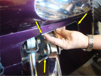
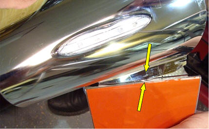
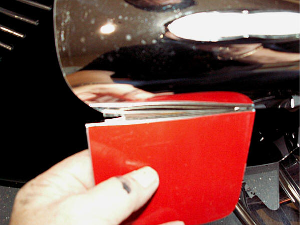
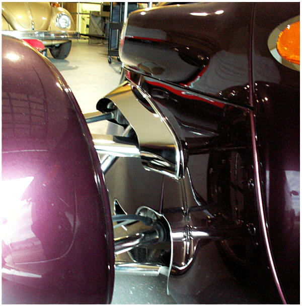
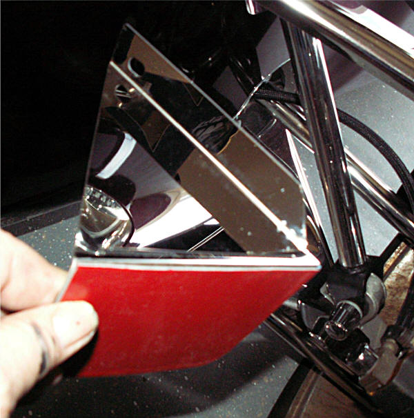
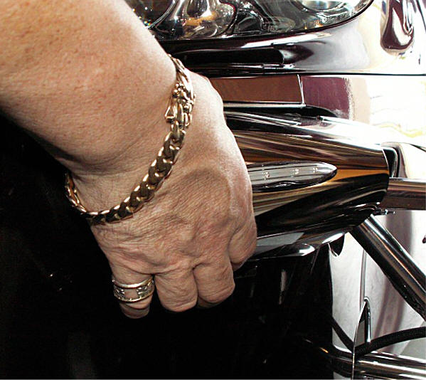
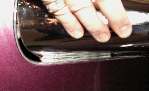
3. You have been provided with two lengths of chrome trim see (Picture 1). One long and one short. Pull the red release liner from the back of the long trim and set the edge directly onto the upper fender ridge at the body seam and press it in place along the front edge all the way under the a arm until it ends. Do the same for the remaining trim at the small opening.
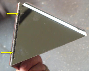
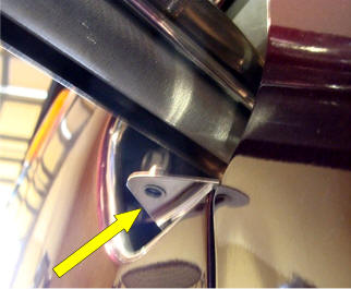
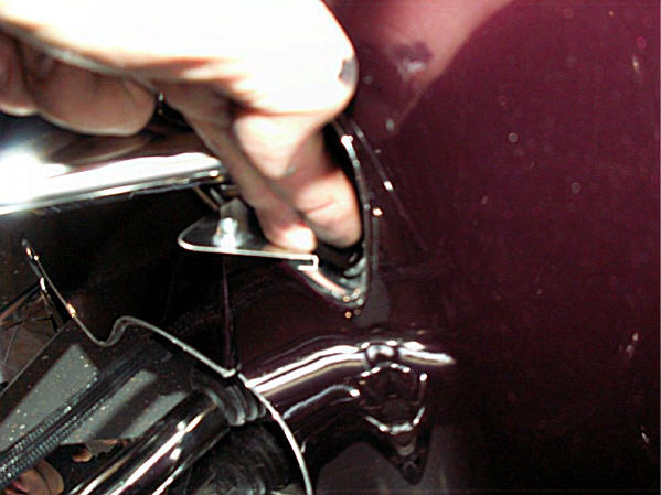
4. You have been provided with two large self stick brackets and two small ones. Before you permanently stick these into position set each of them in place to get acquainted with their position and also to get a feel for just how you will manipulate them into place. You will notice that the large bracket contains a slit running along its length see (Picture 2). It is important to understand that this slit will be the attachment point of the new fillers lower tab and must be completely exposed just inside the fender opening. The smaller bracket must sit firmly against the forward inner fender ridge and lay firmly on top of the chrome trim installed earlier.
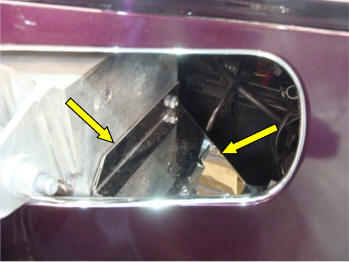
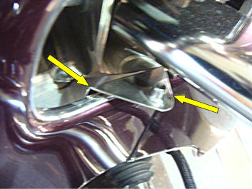
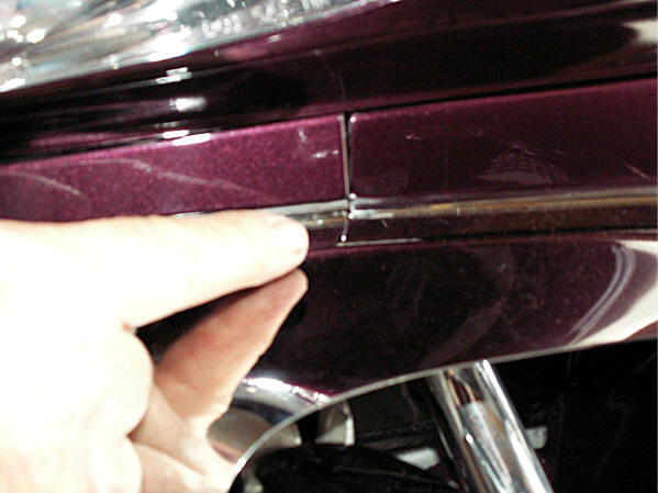
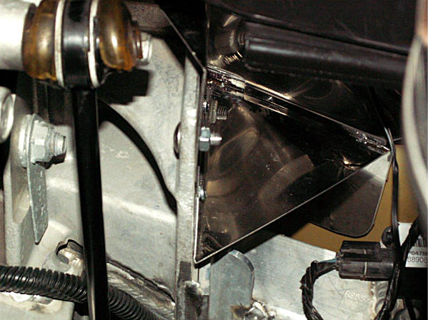
5. Now that you have a good idea of how the brackets sit in place (see Pictures 3, 4, 5 & 6) you can go ahead and peel the red release liner from the back of each of the brackets and set them in place. Press firmly along the attachment tape areas to set and then install the ¼” 20 nut and bolt directly into the factory bumper bracket opening and tighten. Make sure that the small bracket sits firmly against the inner fender ridge see (picture 4).
Picture 7
Picture
8
Picture 9
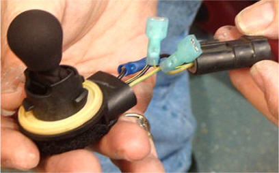
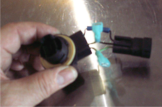
6.
The next
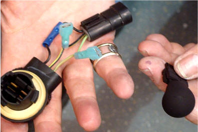
step will be to prepare the electronics. Because you can not directly
replace the factory lighting with LED lights you will need to borrow the
electrical harness from the bumper. Unscrew the factory light lenses
from the front of the bumper and detach the bulb socket. Pull the
harness out far enough to allow you to snip the wires about 2’’ back.
You will also need to snip the female connector at the back end of the
bumper. Strip all the wire ends about ¼’’ back to expose the wire
strands and then twist them nice and tight. You have been provided with
fourteen blue wire connectors and 4 blue female blade connectors. These
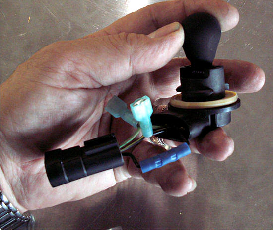
connectors will need to be crimped to the wires as followed. Let’s begin
with the factory bulb socket and female connector. Attach these two
items together by crimping the two black wire ends into one of the blue
connectors. Twist the two center wires together and then crimp on one of
the blue female blade connectors. Do the same for the remaining two
wires (see picture 7) This will leave you with a mini harness containing two female
blade connectors ready to connect to you led lights. The remaining blue
tube connectors have been provided to be used to attach to the exposed
wires at both ends of the bumper harness should you decide to restore
the original bumpers
to the Prowler. Before we connect any wires lets prepare the harness for
mounting.
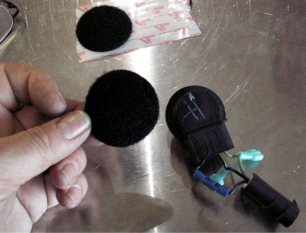
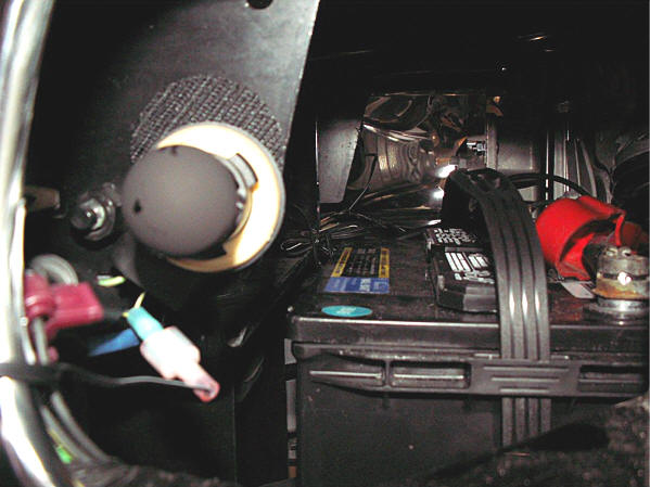
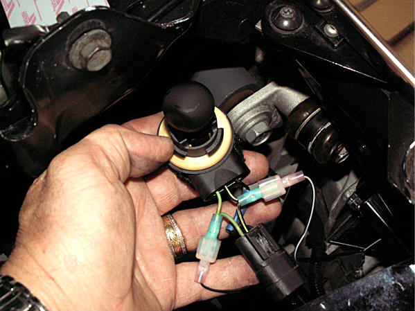
7. You have been provided with two Velcro attachment cookies. Place the furry cookie around the back side of the bulb harness and the remaining hook side directly to the steel bracket just to the inside of the bumper fill opening. This will provide a stable location to mount the new mini harness. Do this for both sides.
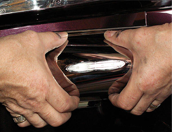
8. Remove the
amber factory light bulb and replace it with the black out bulbs
provided for both sides (see picture 8). This will allow you to retain the factory light
circuit and you will now be able to simply attach the new LED lights.
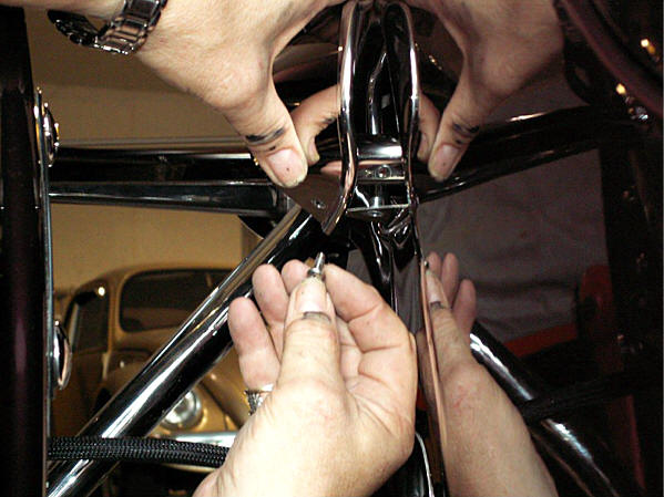
9. Now that
you have made all preparations carefully manipulate the new fairing unit
by sliding the top bracket into the body opening. At this point you will
see that the lower tab of the fairing sits well below the body opening.
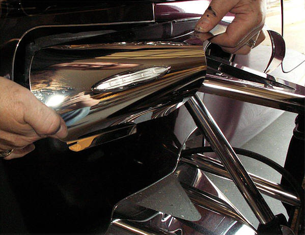
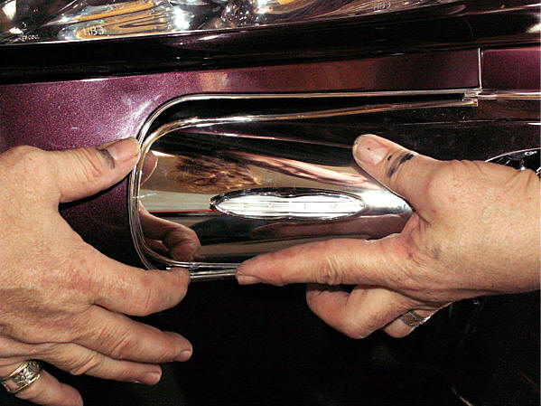
Using some significant force squeeze the roll (see Picture 9) in the fairing enough so
that you will be able to set the lower tab inside the body opening. At
first this will seem like it’s too big and will not be able to fit but
the fact is that if enough force is placed at the roll in the part you
will be able to tuck this lower tab into the opening.
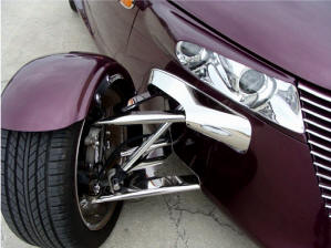
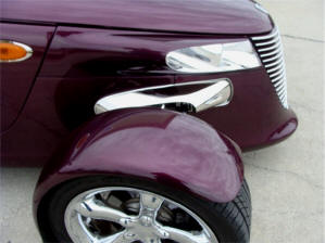
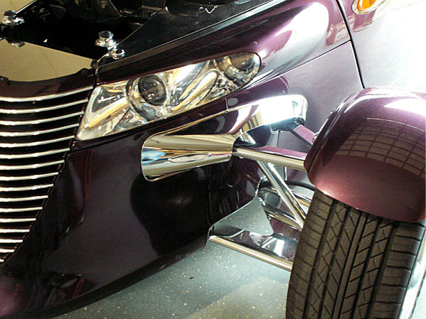
Finished installation Finished installation
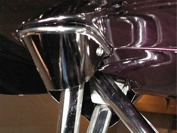
Picture 10 (Bracket only shown removed only to see
the assembly more
clearly. Your bracket will be installed when mounting the
fairing.)
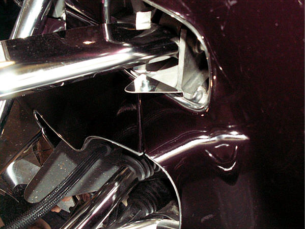
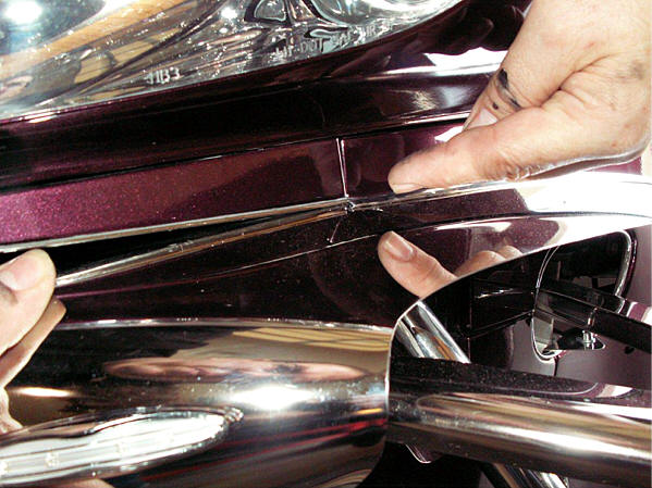
10. Once you have successfully fully inserted the fairing into the opening the next step will be to force the fairings lower tab into the slit of the lower bracket (see Picture 10). You will be able to do this from the inside of the front nose and will take some force to be able to slide the fillers lower tab outward and into this slit. Once the tab has been inserted manipulate the fairing so that the small notch in the tab can be slid forward over the bracket edge locking the fairing and bracket together. This is done in this way to insure that the fairing remains visually nice and tight to the body.
11. With the lower tab and bracket interlocked force the top bracket down and align the hole in the bracket with the hole in the factory bumper bracket and insert the ¼ 20 bolts provided. Finger the nut onto the bolt and then align the outer edge of the filler so that the chrome trim butts up to the chrome trim you applied to the fender ridge earlier. Once the trim is aligned tighten the nut and bolt to lock this position.
12. The next step will be to shape the back half of the fairing to match the body. Twist the back curl in the fairing and align the hole up with the threaded rivet nut attached to the small bracket installed earlier. This initial alignment will expose the areas that will need to be shaped by hand to achieve a nice contoured fit to the body. Although the fairing comes to you pre shaped you will need to further shape the fairing by hand. This will require some significant force in some cases and will render a nice looking fit. Don’t be afraid to roll or twist the fairing if needed to achieve this. The stainless is relatively firm however it is also thin enough to conform to your adjustments. Once you have achieved a nice contoured fit simply lock the filler to the body by installing the stainless 10/32 Philips screw provided. TECH TIP: Although it should not be necessary you can apply a small dab of instant adhesive to the screw prior to install to prevent this screw from backing out of place long term. Once the fairing is installed remove the protective liner.
13. You will notice that the led signal lights have been fitted with male slide connecters on each wire. One wire is solid black this is the ground wire. The remaining wire is black with a white tracer. This is the positive wire. Connect the solid black wire to the wire at the side if the mini harness. Connect black wire with the white tracer to the center wire of the mini harness. NOTE: It is very important that you carefully connect the correct wires together. Connecting these wires backwards may damage the led light. Perform the entire installation procedure exactly for the opposite side to finish the installation. Attach the mini harness to the Velcro cookie mounted earlier.
|
More Photos to help
 piecing together the chrome vinyl
 |

TheProwlerStore.com is a Hot Car Accessories, Inc. site